The flatness and levelness of concrete floors has become a big deal.
If you've ever sat at a restaurant table that rocked up and down, slopping wine out of your glass and causing you to launch a cherry tomato across the room, you know how inconvenient a wavy floor can be.
But in high-racking warehouses, factories, and industrial facilities, floor flatness and levelness (FF/FL) can be a make-or-break issue, affecting the very performance of the building for its intended use. Even in ordinary houses and commercial buildings, an un-flat floor can compromise performance, creating problems with floor coverings and potentially causing hazardous situations.
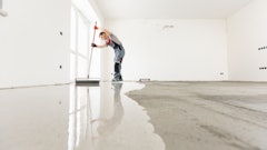
Levelness, how closely the floor conforms to the specified slope, and flatness, how much the surface deviates from a two-dimensional plane, have become important specifications in construction. Fortunately, modern measuring methods can detect levelness and flatness problems more accurately than the human eye. The newest methods allow us to do it nearly instantly; for example, while the concrete is still workable and can be fixed before it hardens. Flatter floors are now more attainable, faster and easier than ever before. It's achieved by the unlikely marriage of concrete and computers.
The Benefits of Flatness
That restaurant table was probably "fixed" by shimming up one leg with a matchbook, effectively filling a low spot in the floor, a flatness problem. If your breadstick rolled off the table by itself, you were probably dealing with a floor levelness issue, as well.
But flatness and levelness have ramifications far beyond convenience. Going back to the high-racking warehouses, an uneven floor cannot properly support a 20-foot-tall shelving unit with tons of stuff on it. It may pose a lethal danger to people working with it or passing by. A more recent development in warehouses, air pallet-jacks, are even more dependent on flat, level floors. These manually-driven devices can lift pallet-loads up to 750 lbs., supporting all that weight on a cushion of compressed air, so that a person can push it around by hand. It requires an extremely flat, even floor to function properly.
Flatness is also essential for any slab that will be covered with a rigid floor covering material such as stone or ceramic tile. Even flexible coverings such as vinyl composite tile (VCT) have problems with uneven floors, tending to lift or detach completely, which may create trip hazards, squeaks, or voids underneath where moisture from floor washing can collect and support the growth of mold and bacteria. Old or new, a flat floor is better.
The Haunted Floor
Waviness in a concrete slab can be flattened by grinding off the high spots, but the ghost of the wave may continue to haunt the floor. You see it sometimes in warehouse stores: floors that are quite flat but appear wavy under the high-pressure sodium lights.
If a concrete floor is intended to be left exposed - designed to be dyed and polished, for example, having a continuous surface of the same concrete material is vital. Filling low spots with a topping is not an option, because it won't match. The only other option is to grind off the high spots.
But grinding into a slab can change that way it catches and reflects light. A concrete surface is composed of sand (fine aggregate), rock (coarse aggregate) and cement paste. When the wet slab is placed, the troweling process shoves the coarser pieces of aggregate deeper under the surface, with fine aggregate, cement paste, and laitance concentrated at the top. This happens whether the surface is absolutely flat or quite sensuously curved.
When you grind 1/8 in. off the top, you remove fines and laitance, powdery material, and begin to expose sand in a matrix of cement paste. Grind further, and you expose cross-sectioned rocks, the larger aggregate. If you only grind into the high spots, those areas will show sand and rock, stripes of exposed aggregate that immortalize those high spots, alternating with stripes of un-ground smooth cement paste where the low spots were.
The original surface has a different coloration than the layer 1/8 in. or 1/4 in. down, and they may reflect light differently. Lighter-colored stripes will look like high spots, with darker stripes between them appearing as troughs, the visual “ghost” of the waviness that was removed with the grinder. Ground concrete is usually more porous than the original troweled surface, so the stripes will also probably respond differently to dyes and stains, making it difficult to end the haunting by coloring it. If you don't flatten the waves during concrete finishing, they may come back to haunt you.
Old School Flatness
For decades, the standard way to check FF/FL was the 10-foot straight-edge method. The straightedge was laid on the floor, and if there were any gaps under it, their height was measured. Typical tolerance was 1/8 in.
This fully manual measuring system was slow and could be quite imprecise since two people will often measure the same height differently. But that was the established method, and its results had to be accepted as “good enough.” By the 1970s, that was no longer good enough.
The advent of high-racking warehouses, for example, made FF/FL precision much more important. In 1979, a numerical method for evaluating these floor properties was developed by Allen Face, a system commonly referred to as floor flatness numbers, or more formally as the Face Floor Profile Numbering System.
A Profile of Profilers
Face also developed an instrument for measuring the floor's properties, a "floor profiler" whose tradename is The Dipstick.
The number system and the measuring method were the basis for ASTM E1155 Standard Test Method for Determining FF Floor Flatness and FL Floor Levelness Numbers, which was developed in collaboration with the American Concrete Institute (ACI).
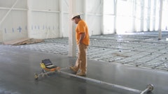
A profiler is a manual tool that an operator walks across the floor, taking data-points every 12 inches. It could, theoretically, profile a floor of infinite size (if you had an infinite amount of time to wait for your FF/FL numbers). It is more accurate than the straightedge method, and it represents the beginning of modern flatness measurement.
Profilers have distinct limitations, however. For one thing, they can only be used on hardened concrete. That means that any deviation from the spec has to be fixed as a callback. High spots can be ground off, low spots can be filled with a topping, but it's all remedial work, it costs the concrete contractor money, and it costs the project time. Moreover, the measurement itself is a slow process, adding even more time, and it is usually performed by a third-party specialist, adding even more cost.
The Modern World
Laser scanning has changed the pursuit of floor flatness and levelness. While the laser itself dates back to the 1960s, its adaptation for construction site scanning is relatively recent.
The laser scanner uses a tightly focused light beam to measure the location of all the reflective surfaces around it, not just the floor but a nearly 360º dome of data-points around and over as well as below the instrument. It locates each point in three-dimensional space. If the scanner’s location has been tied to an absolute location (like GPS data), those points are locatable as specific places on our planet.
Scanner data can be integrated into the building information model (BIM). It can be used for a wide variety of needs such as measuring the room or even creating an as-built computer model of it. For FF/FL compliance, laser scanning has several advantages over mechanical measurement. One of the biggest is that it can be performed while the concrete is still fresh and workable.
The scanner records 300,000 to 2,000,000 data-points per second, and typically runs for one to 10 minutes, depending on the density of information. It works so quickly that flatness and levelness problems can be located immediately after screeding, and they can be corrected before the slab sets. Typically: screed, scan, re-screed if needed, re-scan, re-screed if needed, all in a matter of minutes. No more grinding and filling, no more callbacks. It enables the concrete finishers to produce a flat, level floor on Day One. The savings in time and cost can be significant.
Manual Workflow
From the straight edge to the profiler to the laser scanner, the science of measuring floor flatness is now in its third generation; let's call it Flatness 3.0. The invention of the profiler represented a quantum leap in accuracy and detail of floor data compared to the 10-foot straightedge. The laser scanner not only increases accuracy and detail even further but represents a different type of quantum leap, as well.
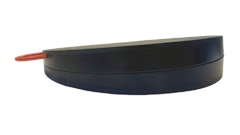
Both profiler and laser scanner are capable of accuracy to the level required by today's floor specifications. However, laser scanning raises the bar, compared to profilers, in terms of speed of measurement, detail of information, and timeliness and usefulness of the result. A profiler takes measurements of elevation using an inclinometer, a device that measures angle relative to level. The profiler is a box with two feet on the bottom, exactly 12 inches apart, and a long handle so the operator can hold it while standing. The speed of the profiler is limited to the speed of a manual tool.
The operator walks in a straight line down the slab, moving the device 12 in. at a time, often covering a distance about equal to the width of the room on each run. Multiple runs in two directions are needed to accumulate the statistically significant sampling that meets the ASTM standard's minimum data requirements. The device takes a vertical angle measurement at each step and converts those angles into changes in elevation. The profiler also has a restriction on timing: it can only be used after the concrete has hardened.
Profiling the floor is usually done by a third-party service. They walk the floor, and then deliver a report the next day, or later. If the report shows any elevation problems that fall outside the spec, they need to be fixed. Of course, with hardened concrete, the fixing options are limited to grinding down, or filling up with a topping, assuming it's not intended to be decorative exposed concrete. Both processes can entail days of delay. And then, the floor will have to be profiled again to document compliance.
Light Speed
Laser scanners work faster. They measure at the speed of light. A laser scanner uses reflections of laser light to locate all the visible surfaces surrounding it. It takes data points in the range of 0.1 - 0.5 in. apart (a much higher information density than the profiler's limited series of 12-inch samples).
Each scanner data point represents a location in three-dimensional space, which can be displayed on a computer, much like a 3D model. The laser scan collects so much data that a visualization can look almost like a photograph. If it's desired, that data can create not only an elevation map of the floor but a detailed representation of the entire room.
Unlike a photograph, it can be turned to display the space from any angle. It can be used to take precise measurements of the space or to compare the as-built condition to drawings or building models. However, despite the enormous information density, the scanner is fast, recording up to 2 million points per second. The entire scan usually takes only a few minutes.
Time is More than Money
Time can be more than money. When placing and finishing wet concrete, timing is everything. It affects the permanent quality of the slab. And the time it takes for the floor to be completed and ready for traffic can change the timing of a lot of other process on the job-site.
When a new floor is placed, the near-real time aspect of laser scanning information has a tremendous impact on the process of achieving flatness. FF/FL can be evaluated and fixed at the best possible point in floor construction: before the slab hardens. That has a range of beneficial effects. First of all, it eliminates waiting for the floor to be completed by remedial work, which means that the floor will not tie up the rest of construction.
If you want to validate the floor with a profiler, you first have to wait for the slab to harden then schedule the profiling service to come to the site and measure it, and then wait for the ASTM E1155 report. Then you have to wait for any flatness problems to be fixed, and then schedule profiling again, and wait for a new report.
Laser scanning happens as the slab is placed, problems are fixed during concrete finishing. The slab can be scanned for compliance as soon as it hardens and the report completed the same day. Construction can continue.
Laser scanning allows you to get onto the floor as soon as possible. It also creates a concrete surface with greater consistency and integrity. A slab that is made flat and level while it's still workable will have a more uniform surface than one that has to be ground flat or leveled by filling. It will have a more consistent appearance. It will have more uniform porosity over the entire surface, which may affect response to coatings, adhesives, and other surface treatments. If the surface gets ground for staining and polishing, it will expose aggregate more evenly across the entire floor, and the surface will probably respond more consistently and predictably to coloring and polishing operations.
From the Scanner to You
A laser scanner collects millions of data-points, but that’s all they are, points in three-dimensional space. To put them to use, you need a piece of software that can process them and present them. Scanner software assembles the data into various useful forms, which it can present on the jobsite’s laptop computer. It offers the construction team a way to visualize the floor, pinpoint any problem, correlate that with the actual location on the floor, and tell how much the elevation must be reduced or increased. In near-real time.
A software package like ClearEdge3D’s Rithm for Navisworks offers several different ways to view the floor data. Rithm for Navisworks can present a “heat map” showing the highs and lows of the floor as different colors. It can display a contour map, similar to topographical maps made by surveyors, where a series of curved lines describe successive elevations. It can also provide documentation of compliance with ASTM E1155 in minutes, not days.
With these capabilities in software, a scanner can be put to good use for a variety of tasks, not just floor flatness. It provides a measurable model of the as-built condition that can be exported into other applications. For renovations, as-built can be compared to historical design documents to help determine if anything was changed. It can be overlaid onto new designs to help visualize the changes. In new construction, it can be used to validate conformance to design intent.
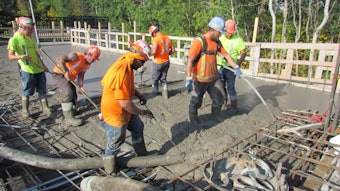
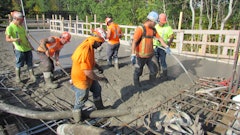
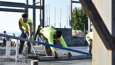 Levelness, how closely the floor conforms to the specified slope, and flatness, how much the surface deviates from a two-dimensional plane, have become important specifications in construction.U.S. Air National Guard photo/Master Sgt. Mike R. Smith
Flattening the Learning Curve
About 40 years ago, a new challenge entered many peoples’ homes, one that has, since then, turned out to be emblematic of modern life. The programmable video cassette recorder, or VCR, forced ordinary citizens to learn to interact with a digital logic system, and millions of unprogrammed VCR’s endlessly flashing “12:00, 12:00, 12:00” attested to the difficulties of learning that interface.
With every new software package comes a learning curve. If you’re doing it at home, you can tear your hair and curse as necessary, and the most that your new software education will cost you is a free afternoon. If you’re learning a new interface on the job, it can slow down a lot of other work, and could cause costly errors. The ideal situation for introducing a new software package would be to use an interface that is already widely in use.
Using What You Know
What is the fastest interface for learning a new computer application? The one you already know. Building information modeling took more than a decade to become firmly established among architects and engineers, but it has now arrived. And, by becoming a standard format for distributing construction documents, it has become an imperative for contractors on the jobsite.
A BIM platform that is already present on the jobsite offers a ready-made channel for introducing new applications, like scanner software. The learning curve gets considerably flatter because key players are already familiar with the platform. They just need to learn the new functions they can pull out of it, and they can more quickly start making good use of the new information, for example, scanner data, that the application provides. ClearEdge3D saw an opportunity to make the highly-regarded scanner application, Rithm, available to a lot more construction sites by making it compatible with Navisworks. As one of the most widely-used packages for project coordination, Autodesk Navisworks has become a de facto industry standard. It is on jobsites across the country. Now, it can present scanner information for a wide variety of uses.
What Information Looks Like
When a scanner collects millions of data-points, that’s all they are, points in 3D space. Scanner software like Rithm for Navisworks is responsible for presenting that data in ways you can use. It can show you the room as data-points, which are scanned not only for their position, but the intensity (brightness) of the reflection and the color of the surface, so the view that looks something like a photograph.
However, you can rotate the view and see the space from any angle, wander around through it like a 3D model, and even take measurements off it. For FF/FL purposes, one of the most popular and useful visualizations is the heat-map, which shows the floor in plan view. The highs and lows are presented as different colors (sometimes called a false-color image) with, for example, red representing high spots and blue representing lows.
You can take precise measurements from the heat-map, allowing you to locate exactly the corresponding spots on the actual floor. If the scan reveals flatness problems, the heat-map is a fast way to find them and fix them, and it is the preferred view for on-the-spot FF/FL analysis.
The software can also create a contour map, a series of lines representing different floor elevations, similar to topographic maps used by surveyors and hikers. Contour maps are good for export to CAD programs, which tend to be friendly to drawing-type data. This could be especially useful in a remodel or retrofit of an existing space. Rithm for Navisworks can also analyze the data and present answers. For example, the Cut-and-Fill function can tell how much material (e.g. cementitious topping) you need to fill the low end of an existing unlevel floor and get it up to level. With the right scanner software, information can look the way you need it to.
Owning Your Time
Of all the ways to lose time on a construction project, the most painful might be waiting. Bringing floor quality assurance in-house can eliminate the scheduling problems, and the waiting for a third party consultant to come profile the floor, and the waiting while it's being profiled, and the additional waiting for a report to be turned around. And, of course, waiting for a floor can hold up a lot of other construction operations.
Owning your quality assurance process eliminates that source of pain. The floor can be scanned in minutes when you want it. You know when it will be checked, and you know when you'll get the ASTM E1155 report (about a minute later). Owning this process, rather than relying on 3rd party consultants, means owning your time.
The Workflow
Using laser scanning for flatness and levelness of new concrete is a simple and straightforward workflow.
- Pour and screed the concrete slab as usual.
- Set up the scanner adjacent to the freshly-placed section and scan. A single placement is usually all that’s needed for this step. With a typical section size, the scan usually takes 3-5 minutes.
- Upload the scan data to Rithm for Navisworks.
- Load the “heat-map” display of the floor data to identify places that are outside the spec and need to be leveled or flattened.
- Locate the corresponding places on the floor. This can often be done by eye using “landmarks” in the room such as a column, pipe, or wall feature. It can also be done with a tape measure using the measurements in the scan data.
- Modify the problem spots on the slab.
- Re-scan. If it’s fixed, complete finishing the slab. If it’s still out-of-spec, locate the remaining problems, work the slab some more, and scan again as necessary. Then complete finishing and cure.
- After the entire floor has been finished and hardened, perform an as-built scan using multiple scanner placements, capturing the entire floor. If the scanner is localized to known coordinates, such as a surveyor’s control point, the scan data can be integrated into BIM for the project.
- Upload the as-built scan to Rithm for Navisworks.
- Generate the ASTM E1155 compliance report. Congratulations on a beautiful floor.







![Glp Porsche 072723 465 64ee42287c29e[1]](https://img.forconstructionpros.com/files/base/acbm/fcp/image/2024/03/GLP_PORSCHE_072723_465.64ee42287c29e_1_.65e88b8589b9c.png?auto=format%2Ccompress&fit=crop&h=135&q=70&rect=0%2C520%2C2250%2C1266&w=240)

